Pickup (12)

Pickup winding - Scavenger style

How I Wind Low and Medium-Z Pickups On the Cheap

CAUTION: I do not wish to pretend I know what I am doing. But this is what I am doing...

You can hear them on my videos.

----------

What NOT to do:

4098376098?profile=RESIZE_710x


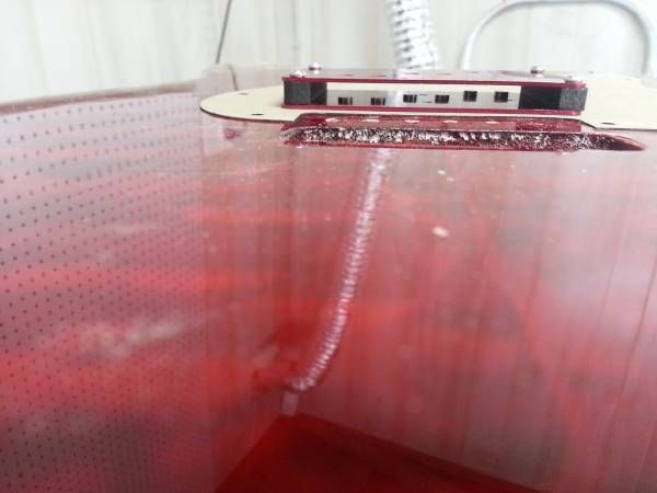
Let's get this out of the way. Do NOT do this.

 Make sure your desk is clean and free of metal shavings or STEEL WOOL. I learned of this hazard from a video done by Dylan of Dylantalkstone.com. As I watched that, it occurred to me that I had just finished taking pictures of winding a pickup, with steel wool in the background. THANKS Dylan. He pointed out what should have been obvious to me. This pickup is still alive now, but I can't help but think of Schrodinger's cat when I play this pickup's guitar...

The Project

I wanted to approach this experiment as I thought someone who had nearly nothing but a few tools and junk to work with. Being a somewhat poor boy myself, I had to compromise on a few things. I wanted to attempt to not only build my first pickup with a cobbled together winder, but do it as cheaply as I could. Better still would be to build the first one with things I had already at the house. I also wanted to do this as primitively, within reason, as I could.

Behold! The Winding Platform!4175338049?profile=RESIZE_710x

9353923862?profile=original

 First off, I built a platform that I could clamp to a larger surface, such as a table or bench. I had this scrap wood and a little MDF and did some gluein' and screwin' it together. I took a manual hand drill I had laying aand just nailed and screwed the drill to the platform with a metal strap and some old screws I had laying around. I used a half-dull ten-year old Stanley miter saw in the spirit of things. I then assembled it using more old screws and glue. never intended this thing to make more than one pickup. I'm a bit of an amature blues history buff and I kinda wanted to simulate what an old sharecropper/bluesman that had an unexpected pickup failure at a house party might do. Deal with what he had. That was the whole point of this exercise. To see if it was an exercise in futility for me, or if I could make it work. I guess corporate America calls it "feasability study". I call it fun. After probably two-dozen pickups, including single-pole diddley bow pups and odd-ball configurations. Almost all of them made noise. And I learned. Boy howdy! Did I learn.

4196099578?profile=original

 A word of caution here. I have seen several people online that use a rechargeable screwdriver or drill motor for winding. I have often wondered how many got halfway through and the drill motor died. Sounds like an aggravation I don't need. Murphy seems to find me too often.

I had an old empty teflon spool laying around and drafted into service for spooling up the wire. I cut a small piece of scrap wood into a square so it would fit in the hole tightly and drilled a small hole through the center and press fit it. That's where the spindle goes. I built a few different forks to hold the spindle and the wire spool before I settled for one.

Winding It All Up

9353923889?profile=original

 As you can see above, the nuts/poles are stuck to  the computer hard drive magnet which is stuck to the winder. I sometimes use earthquake putty to help hold it in place while winding..I usually lead off with about six inches of wire and tape it to the top of the pickup. I then wrap the core four or five times by hand. I check that everything is tight, straight and free of "FOD" Foreign Object Damage and start winding. I then wind until I run out of wire on the spool. I then tape about six inches of that end to the bottom of  the pickup until I am ready to start the soldering. The pictures at the end of this builder's log will show ways of attaching the leads. I have yet to settle on one method as they all have their own unique value and their own limitations and difficulties. If I find one "better" way, I'll post at a later date.

Pickup

My last pickup build was 800 winds of 34 gauge wire from a large 12v Wall wart. I got just under 100 ohms resistance from that. Took me about 20 minutes of winding with frequent quick breaks for a sip of coffee and make sure everything was tight and straight.

9353924456?profile=original

 I now usually take off-cuts from the neck of the guitar to make the top and bottom of the pickup, if I have any big enough. File and sand and sand and sand the wood slices down to 600 grit to make them ultra smooth. Even the slightest sliver in the wood WILL catch the wire and it can get messy real quickly. I didn't always notice when one got caught on something at or near a corner before I wound a dozen winds over it. I just gently got the wire off the snag and wound wire over it. They still work, so... If you break the wire halfway through the wall-wart, well, try not to. I typically get between 300-800 winds per transformer. Mine get from roughly 50-100 ohms, so you don't have much headroom for mistakes. Luckily, 34 gauge wire is a LOT harder to break than 42 or 43 AWG!  I generally use the wire that's between 31-35 AWG from the wall-warts. That's probably why these are fun to wind. Thicker wire = stronger. I have no experience using "proper" pickup wire, but hope to try that someday. I did get some .0035 from one wall-wart, but I dropped it ten seconds after I finished it. SOB! WHY ME!!! WAHH! NOTE: These things don't like to be dropped four feet onto concrete. No amount of whining, cursing, or crying will make it good. I know. I tried all, in that order.

Poles are usually stainless machine screws of various lengths. If you go this route, make sure they have enough ferrous material in them to be strongly attracted by a magnet. Some stainless has no magnetic attraction. I've built with 3/8 - 1 inch screws. I either slap a computer hard drive magnet on the bottom of the nuts or put neodymium button magnets on the bottom of poles. In one, I drilled holes in the neck under the pickup in alignment with the poles and glued the button magnets flush into the neck. Then the pickup was mounted to the top just above magnets. .015 in.? Looking forward to trying real guitar pickup magnets some day. Thousands of possibilities... 

4196933083?profile=original

Some of my first experiments. One is still in a guitar and still working.

I have not wax potted any of the pickups that I have built, and fortunately, I haven't regretted it. I have yet to have much in the way of microphonics in any of the pickups, (tiny amount in some...), except for one that I brushed nail polish on the coils about every couple of dozen or so turns. That one is quite microphonic. It's not even the most powerful. Go figure.

I also twist the lead wires before installation to reduce the chance of interference. With the very low-z, there is already a VERY clean signal produced by the pickup. Some, I have read don't like the sound, but I found that an added buffer, or other type of boost will add color and distortion. A preamp works nicely here... I can plug our BR-600 into it before sending the signal on to our amp and it sounds more like a more conventional pickup, but cleeeeaaan unless effects are added. Or, just add a ton of gain and crank it.

Building the bobbin would be a lot easier if I could get some thinner hardwood stock, but I am using what I have... (obligatory grumble) I usually cut the top and bottom from 1x2 hardwood, often part of the neck. I cut them to the size that I want + about .02 inch in for tolerance. I file or shave the edges to fit the hole in the box when installing. I also build a wooden core. I usually cut the wood with a little excess to file away to give you tolerances for the drilling of the three holes for the poles. If you have a drill press, I would use it here. Make this puppy smooth. I used a little bit of glue to hold the wood core to the top and bottom, taking care to clean up any that oozes out of the gaps. This should help keep the wires out of any tiny gaps that might be there between core and top and bottom. I drill the holes for the poles a bit undersized. I like the screws to be just a bit tight when the whole thing fits together.

4196971371?profile=original

9353925652?profile=original

4196971371?profile=original

The Coil Wire

 There are a lot of sources for enamel wire out there, electric motors, solenoids, relays, etc.. I mostly have experience in taking apart wall-warts because it was the easiest way to access it that I tried. I never came up with an easy way to take one apart other than learning that the plastic case of the wall-wart breaks easier if it is cold. Cold garage works well, but summer probably  won't offer much of that... You can put it in your freezer for an hour or so before bludgeoning it to death if you wish... There are several videos out there on how to take them apart. I don't have any pictures of this process and I don't have access to an old, unused transformer right now. I put the transformer on the anvil of my vise with the seam placed vertical and whack it along the seam. Be careful doing this. If you don't crack the housing,  when you hit it, a light hammer can come back at you, fast! Once you get the cover off, it's relatively easy to see what needs to be done, there is no easy way, I use a chisel to start the outside leafs of thin sheet steel to tap them out of the plastic frame. Once the thin plates start coming out, sometimes a pair of pliers will help.

In the picture below you can see the wood hub I made that goes through the transformer frame. Then place the thing into the wood yoke so it can spin freely while giving up it's wire to the teflon spool. If you have any questions about this or anything else, please ask. 

9353925699?profile=original

The Connection

 My skills at soldering are about average when it comes to automotive-sized wiring, but I have a problem with soldering electronics. First of all, there is this strange sucking noise that starts up as soon as I start to solder the enamel wire of the coil to the leads, and doesn't stop until I stop soldering... Partly because of this, I have tried quite a few tactics to master this elusive task. I can DO this, it's just an iffy proposition and I have to redo it more often than I'd like to admit. For this reason, I am going to highly recommend you do your own thing on this. You are probably more adept at it. I do know one thing. Using a disposable lighter to burn the enamel off the wire works until you get below about .007 of an inch thick, but anything less than that is likely to go up in flames. For the thicker wire, .007 to .011, (thicker wire nets very little volume of sound), I use a lighter, then very fine sandpaper 600+ grit or higher to rub off the ash. For thinner wire, I carefully use the sharpest blade I have to scrape the enamel off and/or use 600 grit and carefully rub it off.

9353925895?profile=original

9353926474?profile=original9353926884?profile=original9353927057?profile=original

Read more…

Three brand new lessons for playing the Blues, tasteful slide guitar & getting the best tones from your cigar box guitars.

NEW TODAY:  Quick Blues Lick of the Week:  The T-Shape Riff   A seriously badass slide-blues riff that uses shapes to explain it...not chords or music theory!  Another great way to kickstart your collection of blues riffs.

Tasteful Hammer-On Techniques:  This is a simple playing style that will develop your rhythmic playing. I use this all the time in concert in various ways. Here's the foundations of the style, broken down in one easy video.

THE BEST ACOUSTIC PICKUP for cigar box guitar...and the simple method of installing it:    I've played every sort of piezo-equipped cigar box guitar over the last two decades and this setup beats them all.  It's what I use in my new line of guitars...and I'll never go back! 

63e8dd7c-5448-4c60-8556-fbec13bf76f8.jpg?width=640

Read more…

We recently posted this Instructable describing how to install a Cortado balanced-out pickup in a banjolele. This pickup runs into a little circuit that balances the signal and matches the impedance to a mixing console -- similar to a preamp or active DI. The instrument plugs straight into a mic line. (The console has to provide phantom power to the circuit.) This provides much wider bandwidth and higher signal-to-noise than you usually get from a piezo pickup.

In short, we simply removed the sound board, stuck the piezo to the head below the bridge, stuck the shielded circuit to the inside of the instrument with Velcro, stuck the mic jack to the outside, and replaced the sound board.

9353862889?profile=original9353863687?profile=original

9353864088?profile=original

Read more…

I'm releasing this under the Creative Commons License - Attribution Non-Commercial Share Alike (CC BY-NC-SA) 

BB77A14F-6EE0-49BE-B0CA-496360D784FB_zpses4swsz0.jpg?width=640

Why build this winder?

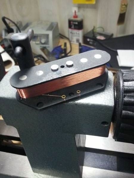
Cost vs performance for starters. Features for another. Want to push your decision over the edge? You can build this winder for $158.00 and have a whole lot of machine for very little investment.

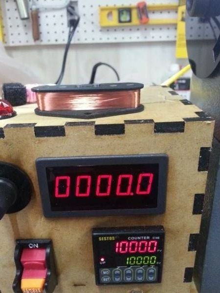
One of the lowest cost and most popular "Pro" winders is $462.90 and it only has a counter; no tach and certainly no autostop. You'll also need to align and tape your pickup to the front of it with carpet tape. Check it out for yourself.

Basic idea and cost breakdown

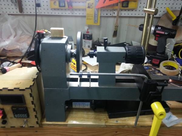
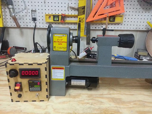
Why a lathe based winder? Safety, speed and superior winds. The lathe provides an ideal turnkey winding platform with the addition of some industrial automation components and a little know-how.

The tail stock of the lathe positions the pickup precisely on the winding plate and holds it in place securely without the need for carpet tape. There are no worries of your pickup flying off the tape and embedding itself in your face.

I've wanted a new winder for awhile, and figured I could make better than I could buy, and do it for cheaper. I reused everything I could from the basic lathe and used off the shelf components to keep this simple and inexpensive. You just program the number of turns, press go and let it rip while you guide the wire. I don’t see the need for an auto traverse, so I didn't make one; I like scatter wound PUP’s.

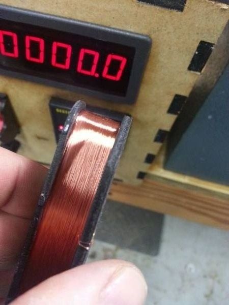
I wound my first pickup in 1986 - this winder incorporates everything I've learned since then and has all of the things I wished all of the other winders had :-). What does that mean? ... it means that it's a stripped down gas can built for speed and it's meant to scatterwind pickups on a professional level. It will wind a pickup in 1/4 of the time of the store bought commercial rigs based on the Schatten design, and it will wind a truer pickup. It will also get away from you and make a clown wig of your expensive wire in that same amount of time as well. Start slow and work your way up to quicker winds. The payoff for your practice? Faster winds produce tighter coils with less microphonics and you can fit more wire on the bobbin if you need to.

I also added a forward and reverse switch for CW and CCW operation so you don’t have to flip the pickup over to do a reverse wind – you can even wind stacked humbuckers without removing the pickup to switch direction between the upper and lower coils.

Most parts can be sourced from Ebay or Amazon (Ebay turned out to be cheaper); just search these descriptions – 

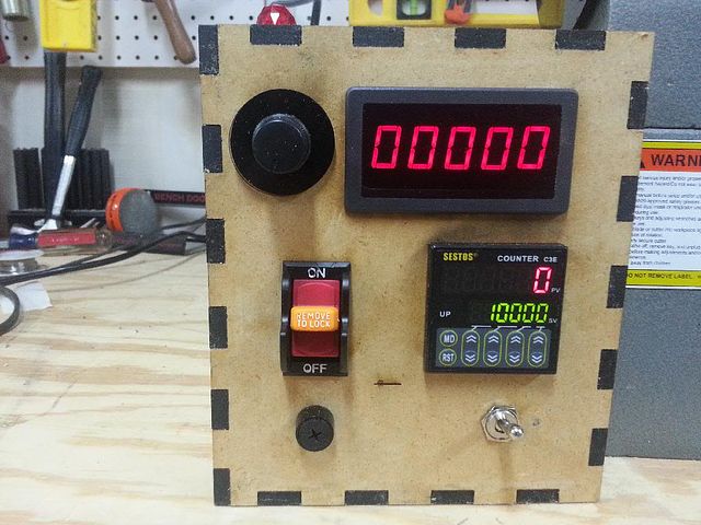
Tachometer - 0.56" DIGITAL Red LED Frequency and Tachometer Rotate Speed Meter DC 7-12V 

Preset Counter C3E-R-220 - 110V 220V 6 Preset Digital counter 10KPCS Relay
(get the 110v - 220v relay version, 12v - 24v version will require an additional 12v power supply)

From Radio Shack - DPDT center OFF switch
This source is just for convenience, just get a DPDT center off switch with spade logs.
Neon Lamp
Again, get what you want, 120V will be the easiest to use. 

The following parts are from www.sparkfun.com
Photo Interrupter GP1A57HRJ00F Breakout Board

Photo Interrupter GP1A57HRJ00F

Resistor 330 Ohm 1/6th Watt PTH


Opto Interrupter Disk

For those who would like to make the winder but might have trouble making the opto interrupter disk... here's the file in a format ponoko.com likes. Just upload it to them and they'll cut you one. 


Their current pricing to make if for you is $5.33, so not bad at all. Make sure to specify these options - 

Acrylic - Black
3.0 mm
P1 - 181.0 mm long x 181.0 mm wide
Making: $1.83
Material: $3.50
Total: $5.33

6605FB24-D62E-4EDC-9FE4-B8847914DA48_zpsqsnilx9e.jpg?width=640


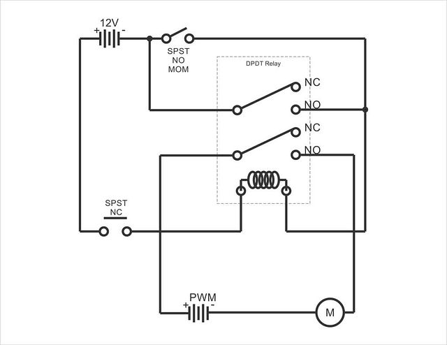
Schematic and control circuit - click to open the PDF - this is the layout to use if you're using the Harbor Freight lathe as your platform. 

Theory of operation

Note:This is here for those that are interested in the how and why; it's not necessary to understand this section to build the winder. Also - this is rather conceptual in as much as the a low voltage relay is built into the counter already. You would only need to add an external relay like this one if you need to switch a large current load directly... a motor for example. Most controllers will use a low voltage trigger or inhibit line like the Harbor Freight lathe. 

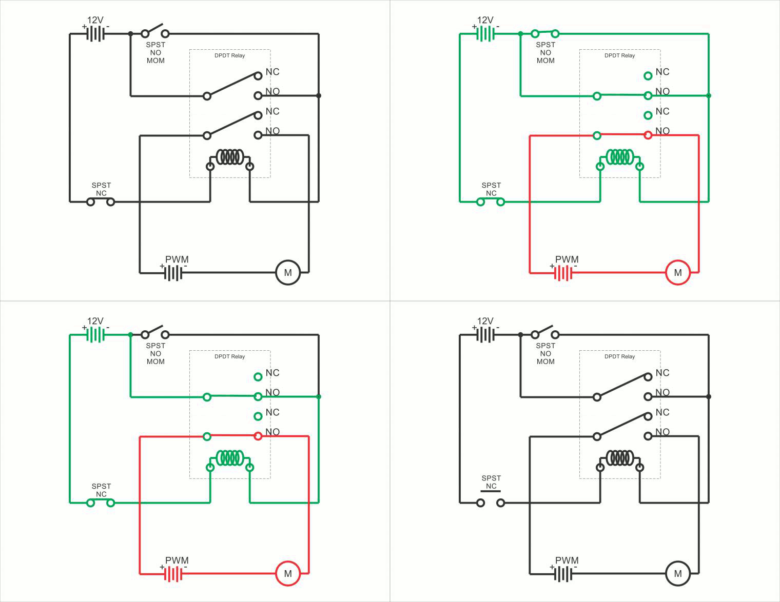
My design relies on a latching circuit for basic operation – so here’s how that works…

Here’s an animation I did to illustrate the basics of a latching circuit – you’ll find that this is directly relatable to the schematic posted below. 

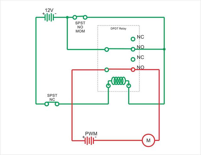
latching_animation_zpsz61m6bzo.gif?width=640S1 is a momentary action switch, so it returns to it's original position after you press it, but while pressed, this is what the circuit looks like... S1 is pressed and latches the upper portion of the relay, both armatures move as one and the lower armature circuit completes the circuit between the motor and it's power supply, and the motor begins to run.

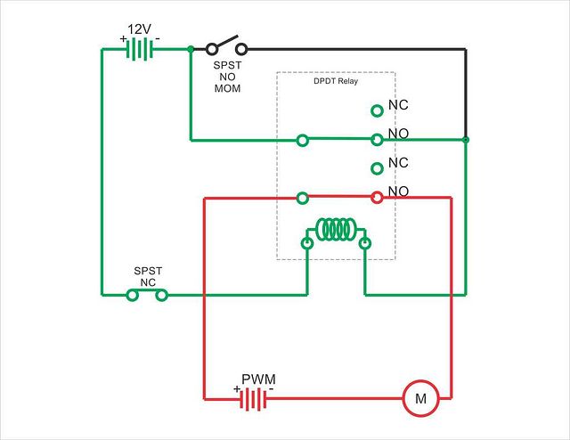
latching2_zps7ngcjuio.jpg?width=640S1 is released, and through the nature of the circuit, the relay remains "Latched". The coil is still conducting and pulling both of the armatures into a closed condition and the motor and it's power supply are still bridged so the motor continues to run. 

latching3_zpsieesipor.jpg?width=640The momentary switch labeled S2 in this schematic represents the "normally closed" outputs of the counter's relay. Imagine that you have the counter set to spin until it reaches 10,000 winds and it gets there. The Normally closed contacts on the counters relay open, thus breaking the electron flow through the coil, thereby releasing the armatures, severing the circuit between the motor and it's power supply and the motor stops spinning. The circuit is now in a rest state and "unlatched". The circuit is reset and made ready to run again when you press the reset key on the counter, thereby closing S2. 

latching4_zpscb9tebsx.jpg?width=640 

Interfacing with the Harbor Freight lathe –

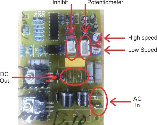
interface_zps7cwgrwx8.jpg?width=640This is the motor control board for the Harbor Freight 8x12 wood lathe and probably several others..... 


Here's how everything works - 

DC out - motor for the lathe
AC in - AC input from wall (mains)
Potentiometer - (controls lathe min-max speed)

Inhibit - what we're using to stop the motor at the specified number of turns. Most commercial DC motor controllers have some variation on this theme... some provide braking and others, like this one, kill the DC voltage going to the motor. Other variations of lathes use this input for a type of safety circuit or to make sure chip guards are in place. 

For some unknown reason of applied goofiness in engineering, on this lathe, this line was attached to a momentary push button switch labeled "circuit breaker reset"... whatever.

*** In this design, it's now connected to the "Normally Open" outputs on the counter module - when those outputs close when the preset count is reached, the motor controller shuts off. ***


As for the High and low speed adjustments, they do exactly what they sound like :-) - adjust the lower one to have the motor start at 0 RPM's instead of a "really not appropriate for this application" 750 RPM.


Opto interrupter disk and opto interrupter for counting winds

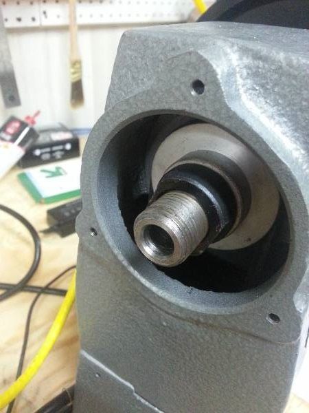
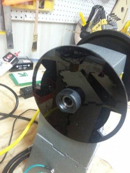
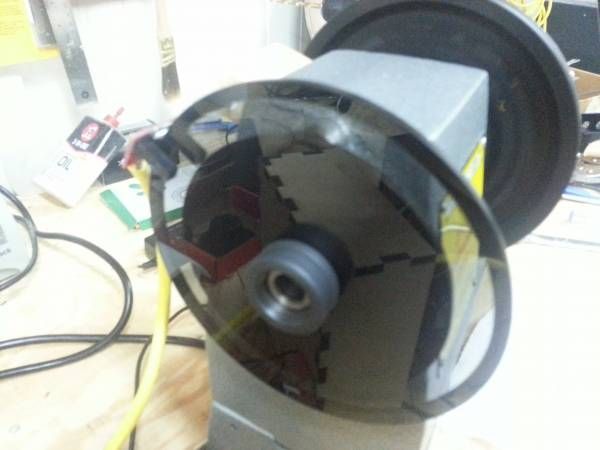
Here's a view of the left side of the lathe with the plastic bell housing removed showing the opto interrupter disk I cut and the assembly steps –

Spindle assembly ready for optical interrupter instillation (remove the plastic bell housing and the outer most jam nut) - 

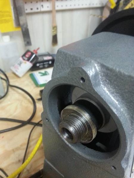
opto_ready_zpsfljwasgc.jpg?width=640Place spacer on spindle shaft (I laser cut this spacer, but you could stack washers to achieve the same effect) -

shaft_spacer_zpsezqolamm.jpg?width=640Spindle assembly ready to go with the new opto interrupter disk and outer jam nut installed – you need 2 windows on the disk and it needs to be well balanced, 3000 RPM is unforgiving in this area.

opto_installed_zpsdbui2fon.jpg?width=640Under power at 3200 RPM – smooth as silk.

under_power_zpsjlwxjw2m.jpg?width=640Opto Sensor & Winding Bar

This photo shows the opto sensor on the top of the lathe – it just attaches with a magnet and hangs over the disk. I’ll take better pics of this area as soon as I get a chance.

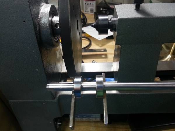
The winding bar is made from 10mm stainless stock (what I had laying around). You just need a piece of round stock that will fit in the opening of the cross slide (included with the lathe).

opto_zpsyjsrw2ba.jpg?width=640

Magnetically adjustable wire guides

This innovation is kinda cool and works very, very well. The wire guides are 10mm ID ball bearings held in place and adjusted by magnets (way easier to adjust position then using set screws). Set screws are a pain, and not needed. It's super handy to be able to adjust the wire guides without fuss mid wind.

Buy ball bearings that fit your round winding bar from the previous step. McMaster Carr is a good source.

winding_bars_zpsmofxxako.jpg?width=640


Handwound pickup goodness...

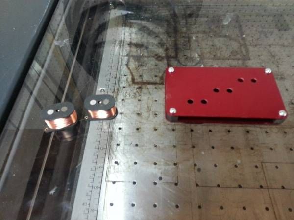
This winder is capable of producing some truly spectacular pickups - if there's interest, I'll do a start to finish on pickup making, from making the flat work from scratch (just like the ones above) to potting the pickup in wax and all points in between.

d5d1b5a0-25d4-4fcb-96c1-1c2ef2236c75_zpsagodm7ns.jpg?width=640

telep2_zpsbzhut9qe.jpg?width=640

telep3_zpsthlrkbgr.jpg?width=640

custom_zpsr77vlrhm.jpg?width=640

custom2_zpsm7e9dyap.jpg

402b114e-9767-4819-89cd-8a79bbfb1ac1_zpsqsrm9rxf.jpg?width=640

Read more…

Guitar #10 rebuilt

This was my 10th guitar, and my first serious attempt at a 4 stringer:

9353811067?profile=originalI was never really happy with it: the box I had made (out of 6mm ply and 3mm sapele for the soundboard) was big and a bit unwieldy, I had also originally intended to have only 9 holes on either side but unfortunately a beer and drill related accident meant I had to add more to make it symmetrical.

I also had a couple of problems with this guitar - the neck was not secured well enough to the box and there was some uplift on the neck. Not a bow in the wood as such, but it was making the action uncomfortably high. I also managed to leave it leaned against an external wall in very cold wet weather, and the damp made the soundboard all spongy and raised the grain on the neck. You could say I had some bad luck with this build.

I worked on a couple of other projects for a while and came back to this one, with the intention to rebuild the box. I started by making a pickup for it:

9353812098?profile=original

Well, I made a couple of pickups... the one on the right is obviously the one for the 4 stringer. I used a scrap of oak from the fretboard for the top of the bobbin. 6400 wines of 42AWG and alnico 5 magnets. I was going for a nice mellow tone on this one so I didn't want to overwind.

I had a couple of pre-made plain craft boxes left over so I planned to use on of those. The only problem is they don't sound good (very thick lid etc). I planed off the original lid and made a new one out of the same solid sapele stock I used for the original. I used a bit of Rustin's walnut stain on the box to make it look a bit more interesting.

9353812487?profile=original

This pic shows the underside of the soundboard. I glued two 100mm strips together and used 5x6.5mm spruce strips for the bracing. The hole at the top is for the pickup. I added a scrap of 6.5mm thick sapele to act as extra support under the bridge to counter the extra tension of 4 strings.

I glued the new lid on, attached the neck (very securely) to the bottom of the box and finished everything with a few coats of Danish oil.

9353813859?profile=original...and that's the finished article; 4 strings tuned GDgb, 4 pole pickup, volume & tone control.

9353814079?profile=original

Sound holes - just 6 this time, I used 6mm inside diameter grommets from a leather craft supplier on eBay. You might notice the magnets are a bit wonky on the pickup. Not intentional! Sounds fine though.

9353814654?profile=original

The bridge is made from a scrap of oak from the fretboard and a tiny strip of bone from a guitar saddle blank (I get 4 CBG bridges from one blank). I just use a drill to make the bridge 'arches' and sand it to a point. Volume (A250k) and tone (B250K) control with a .047uF Sprague Orange Drop capacitor. The tailpiece is a bit of sapele with a piece of brass sheet glued to it. The string ferrules are bike spoke nipples. The copper plate is connected to the ground on the back of the volume pot.

9353814496?profile=original

I loved working with sapele for this neck. Compared to oak it cuts like butter with a spokeshave and smells lovely. I'll definitely order some next time!

To make this headstock I cut a section out of the top of the neck blank and glued it to the bottom, then shaped it with rasps and sandpaper.

That's it. Now I can get back to playing it!

Rick

Read more…

My continued adventures in pickup building

If you haven't read the last instalment:

http://www.cigarboxnation.com/profiles/blogs/my-first-2-weeks-of-pickup-building

...so, the problem I was left with was that I hadn't grounded the strings and both my tailpiece and bridge are made of wood (and bone, neither great conductors!)

I decided to go for a pretty drastic solution. Here is the problem:

9353808473?profile=originalI took the strings off and took a saw to to the tailpiece... Here is my solution:

9353809485?profile=original

This is part of a hanging fixture ( one of the advantages of working in a department store, few though they are), I used a Dremel to cut it to the right size and drilled a few holes to mount it to the back of the guitar and 3 to hold the string ferrules. I have used bike spoke nipples for these. At 20p each at my local bike shop they're a lot cheaper than real string ferrules!

The idea was to solder a wire to the inside of the tailpiece and connect it to the ground on the back of the volume pot. What I hadn't considered is that it's bloody difficult to solder to stainless steel. I didn't have any flux to hand so I cheekily superglued a strip of copper foil tape to the tailpiece and soldered the wire to that... hopefully this will work!

9353810469?profile=original

So here's the new tailpiece. I actually never liked the original so wasn't too sad to see it go. The sound still seems to be just as nice so I'll take that as a success...

I soldered the wire onto the back of the pot and checked all the connections. I plugged it in and the loud continuous buzzing had all but gone! I now had a slight buzzing which went away when I touched the strings... after sending myself mad Googling this for a couple of hours I found a lot of conflicting advice, mainly:

  1. The guitar is not grounded properly
  2. The guitar is grounded properly, and it is your body causing the interference. The hum goes away when you touch the strings because you complete the ground loop
  3. The guitar is wired correctly, but the soldering job is bad

Now I'm perfectly ready to accept that I'm not very good at soldering, as I have no previous experience with it. However I figure that if everything works, the soldering should be fine, right?

I eventually decided to believe number 2. I noticed that there was very little hum when I left the guitar in the middle of the room, and stood away from it. I also noticed that not having my amp plugged into a socket with a PC, Laptop and a baby monitor made a big difference. If anyone reading this has any other ideas I'd love to hear them!

So, I still had one last trick up my sleeve - my copper foil tape. I thought I'd give it a try on one of the new pickups I made following (I thought) Bob Harrison's suggestion.

9353810690?profile=original

So I have potted the coil, wrapped it in a few layers of plumbers' tape, and then wrapped in a layer of copper foil. I then ran a jumper lead from the ground connection (start of the coil) and connected it to the foil. I also used a little lump of solder to seal the foil shut in case the glue deteriorates over time.

Somewhat foolishly, I whacked the pickup in the guitar without checking it first... when I plugged it in, it didn't work. No signal, some buzz, but definitely no sound coming from the strings. Without really bothering to figure out why, I took it out and removed the copper foil (trying to grasp electronics by this point was making my head hurt). After ruminating on this over the last couple of days, I think that maybe I shouldn't have connected the ground wire to the foil and the start of the coil. If the ground is the path of least resistance, maybe I have just forced the current directly to ground... again, any feedback on this would be appreciated!

Sure enough, after removing the foil and the jumper lead, the pickup worked again. I strung it up, closed the access panels and called it a day. Some noise, perhaps, but hardly too offputting for a first attempt!

9353811878?profile=originalSo there it is! Reasonably happy with it - will post some vids soon. Next step is to start messing around with tone pots and capacitors!

...and here's a video - let me know what you think!

Read more…

My first 2 weeks of pickup building

I decided before Christmas I wanted to have a go at making my own magnetic pickups, and put it on my to-do list for the new year. I studied this guide http://www.instructables.com/id/Make-A-Guitar-Pickup/ extensively and ended up taking inspiration from a few other sources to come up with a design, here is the process:

I ordered a 500g spool of 42awg (0.063mm) copper magnet wire from Brocott's (UK supplier) and a couple of packs of alnico 5 rod magnets (5x19mm) on eBay. I had some 3mm sheets of sapele so I figured I would use this for the bobbins.

9353804877?profile=originalThese were the first 2 bobbins I finished, I fixed the magnets flush with the top and bottom with a dab of superglue and drilled 2 holes for the start and end of the wire. It is really important to sand the inner surfaces of the bobbins completely smooth and free of any tiny burrs as the wire will get caught. Best case scenario you'll have to unwind several hundred turns, worse case the wire will break and you'll have to start over.

9353805083?profile=originalThis is the winding jig I made. I did try a sewing machine first but I felt that I didn't have enough control. This is just a hand-cranked drill clamped to a desk, with a block of wood fixed to a dill bit. I attached the bobbin with an adhesive pad. One turn of the handle is about 4.2 turns of the bobbin, so I would do 50 turns, check for any tangle or loose winds, then do another 50 and mark a tally. When I had done 19 x 100 revolutions of the handle, I had roughly 8000 turns on the bobbin. This took about 30 minutes altogether.

I then decided to make a hole in the soundboard of one of my guitars to check for the fit. I use a neck-through design so I also needed to chisel out a recess for the bottom of the pickup to sit in.

I used a drill to start the hole, then fed a coping saw through to cut it out, then sanded etc. I then realised I hadn't thought of how to mount the pickup, and after looking at pages of pickups on Google images, I decided to start over and go for a top-mounting design. (Thanks to Mr. Crocker - an endless source of inspiration!)

9353805862?profile=originalThese were mark 2. I made the tops of the bobbins larger than the bottom, so I could screw them into the soundboard through the top, covering up the hole for aesthetic and acoustic reasons. I also replaced the holes for the start and ends of the coil with small screws. I used steel screws for these but I do not recommend it - it is very tricky to solder onto them - as you can see:

9353806469?profile=originalHmmm... not looking too great. Soldering was very difficult as I needed to melt off the enamel coating on the copper wire before the solder would stick. However I checked the connections by attaching a jack and plugging it in and it did work! Next step was potting.

9353806287?profile=originalThis is a double boiler I constructed to melt the wax. I put about 600g of parrafin wax pellets into a kilner jar, placed a block of wood underneath so the jar was not in contact with the heat source and lashed the top of the jar to the sides of the pan with rubber bands. I filled with water up to about 1" from the top level of the wax and used a meat thermometer to gauge the temperature (which needs to be about 65c). I should add that I have an electric hob, and I think this process would be quite dangerous with an open flame. (This is so far the only advantage to an electric oven I have ever found).

Once the wax had all melted, I wrapped the lead wires from the pickup around a screwdriver and rested it on top of the jar, so the pickup was suspended in the middle, not touching the sides. The idea here is to wait until the bubbles stop rising and the coil will be saturated. I should add that the wood I used also took in wax - and bubbles came off that too. I have it about 20 minutes, took it out, wiped the excess from the bobbin and let it cool. I then wrapped round some PTFE plumbers' tape to protect the coil.

Then it was time to wire it up and put it in the guitar:

9353807252?profile=originalAs you can see, I attached the pickup with 4 small screws. The clamps are there because I had to re-glue the lid on the box.

I then strung it up and plugged it in.

Hmm... not much volume, and lots of buzzing. I replaced the bridge with a pencil, to make it much lower, and the sound was louder - the pickup was too far from the strings. I also had not grounded the strings (which is a whole other problem as my bridge and tailpiece are both wood. Back to the drawing board again!

Pickup Vol Tone Jack

As you can see from Ted's diagram, the ground wire needs to connect the pot with the strings. I am planning to replace my wooden tailpiece with a metal one.

9353807661?profile=original

This is the new pickup I made last night. As you can see the top of the bobbin is much thicker, 6mm this time (an offcut from a sapele fretboard). The termination screws are now brass, so will be easier to solder. I also used a craft knife this time to scrape off the enamel coating, so soldering should be much easier. My next step is to pot it in wax and then wrap it with some copper foil tape, which just arrived yesterday. I will solder a wire from the ground on the pickup to the outside of the copper tape (thanks Bob Harrison for this tip). This combined with grounding the strings should have much better results, so fingers crossed.

I'll let you know how it goes!

Rick

[Part 2 here now: http://www.cigarboxnation.com/profiles/blogs/my-continued-adventures-in-pickup-building]

Read more…

Les Paul Jr. Appreciation Thread

Besides CBGs, I have taken to buying el-cheapo plywood Les Paul Jr. copies on Craigslist and modding them up.  They're easy to work on because the wiring's simple and they have a bolt-on neck.  Here's one I got for $80 including the case:

9353738287?profile=original

First thing to do is properly route the pickup cavity for a full-size P90:

9353739880?profile=original

Here's the new rout shielded and ready for the new pickup:

9353740280?profile=original

Now to fit a cheap, no-name Bigsby and chrome pickup cover: 

9353741656?profile=original

Strip and refinish the neck:

9353742274?profile=original

I used 10 coats of tung oil on this one, it makes for a really nice feel:9353743262?profile=original

Clean out the neck pocket:

9353743894?profile=original

Rerout the control cavity and replace the junky Asian electronics with CTS and Switchcraft:

9353744688?profile=original

Re-dye the fretboard, replace the tuners with GFS tulips, new speed knobs, a new nut...

9353745471?profile=original

...and....


Voila - a smokin' little beater you can gig with:

9353746053?profile=original

Cheers, Brian

Read more…
Here is how I do a simple piezo pickup
A trip to Radio Shack will get you the piezo and 1/4 inch mono jack. They are in a drawer case towards the back of the store and most stores usually have them in stock. The piezo you are looking for is the 273-073 and costs 2$ and the jacks are #274-255 and are two for 4 You can also pickup a 25 or 30 watt soldering iron and some fine(thin) rosin core solder here or go to Harbor freight and save some money. Its all chinese junk anyway. If you use a damp paper towel or sponge and keep the soldering iron tip clean it will last a fairly long time.
Keep it tinned (heat the tip and run some solder on it before soldering) Cheaper and easier to wear out a cheap iron and replace unless you're going into business. Do NOT tighten up the little screws on the barrel too tight as they hold the heating element in. Do not remove these screws and pull as it will junk the iron. (common mistake) Give the iron lots of time to heat up. It might take it ten or more minutes to come up to temp. This is normal for a low watt iron and you certainly don't need more watts. Too big an iron will burn the insulation off and melt plastic not to mention stink. Speaking of stink, ventilation is good as the fumes are not very healthy to breathe. (just a small fan blowing across you will do the trick)
If you go to Harbor Freight you can pickup a "helping hand" for only four bucks. (11$ at Radio Shack) and also save considerable on the solder and soldering iron.
Here are the URL's
http://www.harborfreight.com/cpi/ctaf/displayitem.taf?Itemnumber=47887
soldering iron 5$
http://www.harborfreight.com/cpi/ctaf/displayitem.taf?Itemnumber=95861
solder 3$
http://www.harborfreight.com/cpi/ctaf/Displayitem.taf?itemnumber=319
Helping Hands 4$
The 273-073 piezo comes suspended in a plastic case as its original purpose is to be a buzzer. Since we want it to pickup the sound from our guitar and send it to our amplifier it needs to come out of the case. I have put together a picture story line to illustrate this. I take a pair of pliers and grasp the ear on one side of the case -squeeze and snap the ear and a piece of case off. You have two ears so two chances to get a good hole in the box to pry the top off with. I insert a pocket knife tip or small screwdriver in and slide it right under the plastic top so it misses the piezo completely - then pry the top up and it will pop right off. Careful the Piezo is suspended in there but its close to the top. Then stick a blunt small screw driver in the hole in the bottom of the case and gently push up. The piezo will pop right out with very light pressure. DO NOT BREAK IT by applying to much pressure. Easy does it. Now you can strip the insulation off the wire back a bit and twist the the strands into a single smooth wire. Insert it in the jack and twist it up tight so there is a half decent mechanical connection black goes to the center ring ground terminal on the jack and red goes to the lug that leads to the tall center pin part. Once twisted up tight plug the iron in and let it heat for ten or fifteen minutes. Tin the tip by melting a small amount of solder on it. Stick the tip in the hole on the jack and wait a few seconds then touch the solder to the tip where it came thru the hole and or to the wire itself. The tip heats up the parts to be soldered and then the solder "runs" up the wire and into the joint. If its done correctly it will all be silvery smooth and fairly quick. If the joint is not hot enough you will get a cold solder connection which is BAD. You do NOT melt the solder and drip it onto the wire or terminal. If the wire and terminal are hot enough the solder wicks up the wire as it melts - nice smooth and strong. Its not necessary to add wire to the ones I have built nor to put any switches in the circuit. I mount mine to the neck as it goes thru the box close to the bridge - I use foam mounting tape that sticks the brass side of the piezo to the neck - I use two pieces side by side to get it wide enough and then cover the top with two more pieces side by side to cover and buffer the piezo. This makes a nice clean installation and its extremely strong. Its also really buzz free. The foam mounting tape is double sided "Duck" brand 3/4 inch by 22 ft and 1.5 inches holds a quarter pound. Mounting the jack to the box typically makes me drill two holes - a larger one half way thru the box then a smaller one all the way thru. I have not had good luck keeping these tight enough yet and intend to use gel super glue liberally on the next installs to see if that will help.
When I get time I will put together another blog to illustrate how to double these piezos up reduce the impedance to closer to what a standard amp wants to see. Basically they are wired in parallel so that each set of leads goes back to the jack - so it would be a pair of reds and a pair of blacks coming back to the jack to use double piezos. Series doubles the impedance and parallel halves it. Parallel has a very desirable reduction in impedance. Another subject worth exploring is shielding the leads by wrapping copper foil around the wires and grounding back to the ground lug. This stuff is a bit tricky and care needs to be taken not to set up any ground loops. I need to take more pictures to correctly illustrate this.
Hope this all helps with any amateur soldering and piezo destructing. Comments and questions welcome - Bill

Fresh from Radio Shack, These are in a parts cabinet towards the back of the store. Piezos in one side and jacks in the other. Do not let the kids at radioshack BS you they don't know what is in the store. Almost always in stock. Look for them. 2$ each.


Piezo in plastic buzzer case also removed from case - brass side and ceramic side shown. This is what we want.

The one at the bottom of the picture is busted, I tried to solder the red positive wire back to the ceramic - overheated it and it broke. Probably not worth trying - these also do not bend !!

Grasp the case top and bottom on the edge right at an ear and twist a chunk off. The objective is to break a the edge of the case open so we can remove the top. (without breaking the piezo)

Just got a small bite - its enough though - I can get a screwdriver blade in there and if I needed to I could break the other ear off and get piece of the side too. Two chances to win this game.

Stick a narrow screwdriver or stiff knife blade in there right under the top and pop the top off. Stay close to the top so you don't bend the piezo. Its suspended down a smidge anyway.


And off pops the top. There is the piezo ceramic side up - brass side down. On the other side is a hole to let the buzzing sound out. Perfect to stick a small dowel or screwdriver in and nudge the piezo up. Gently!!


A gentle push up and there is the edge of the piezo, finger food now.

Another shot of the edge of the piezo up where it can be grabbed and the top removed.


The prize - a nice piezo transducer with leads factory soldered on . notice the red positive goes to the ceramic and the black ground goes to the brass base ring

Pair of 1/4 mono jacks - the center ring gets the black ground wire. The tall part contacts the long pin on the cord and it gets the red wire. Thats the left side terminal on the bottom jack.


Jack with leads from piezo soldered on . The black goes to the center ring - these solder joints are too large and would make an electronics tech sneer but they are well done and solid connections if not pretty. You can do this well with a minimum of practice. It works!

All soldered up and ready for a cigar box. No switch is necessary and the leads have been long enough for me to make them work every time so far. Simple down and dirty. There are better ways but no simpler cheaper way and it does work !!

ten dollar soldering station with jack held in extra "hand" This is the four dollar helping hand from Harbor freight - the five dollar soldering iron and the the dollar solder from the local discount store. I am not counting the workbench (scrap shelf board)

Another shot of my soldering rig - keep the tip wiped down with a damp sponge or damp paper towel - keep it tinned. I have never tore one up. Cheap but adequate for this kind of stuff. Probably wouldn't work on a LM386 project but thats a different story.
Read more…