I'm releasing this under the Creative Commons License - Attribution Non-Commercial Share Alike (CC BY-NC-SA)
Why build this winder?
Cost vs performance for starters. Features for another. Want to push your decision over the edge? You can build this winder for $158.00 and have a whole lot of machine for very little investment.
One of the lowest cost and most popular "Pro" winders is $462.90 and it only has a counter; no tach and certainly no autostop. You'll also need to align and tape your pickup to the front of it with carpet tape. Check it out for yourself.
Basic idea and cost breakdown
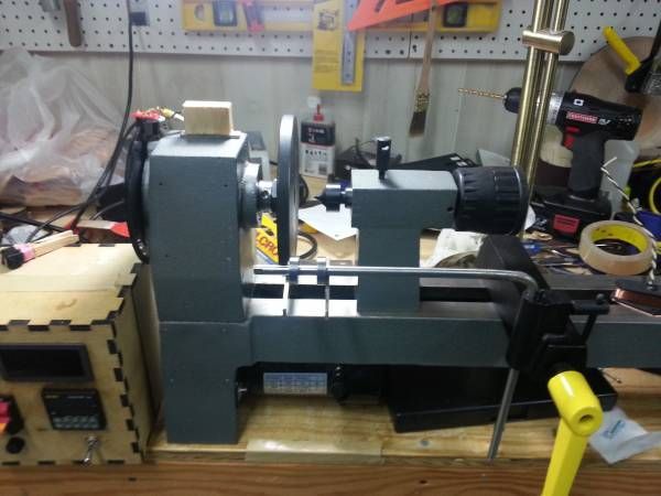
Why a lathe based winder? Safety, speed and superior winds. The lathe provides an ideal turnkey winding platform with the addition of some industrial automation components and a little know-how.
The tail stock of the lathe positions the pickup precisely on the winding plate and holds it in place securely without the need for carpet tape. There are no worries of your pickup flying off the tape and embedding itself in your face.
I've wanted a new winder for awhile, and figured I could make better than I could buy, and do it for cheaper. I reused everything I could from the basic lathe and used off the shelf components to keep this simple and inexpensive. You just program the number of turns, press go and let it rip while you guide the wire. I don’t see the need for an auto traverse, so I didn't make one; I like scatter wound PUP’s.
I wound my first pickup in 1986 - this winder incorporates everything I've learned since then and has all of the things I wished all of the other winders had :-). What does that mean? ... it means that it's a stripped down gas can built for speed and it's meant to scatterwind pickups on a professional level. It will wind a pickup in 1/4 of the time of the store bought commercial rigs based on the Schatten design, and it will wind a truer pickup. It will also get away from you and make a clown wig of your expensive wire in that same amount of time as well. Start slow and work your way up to quicker winds. The payoff for your practice? Faster winds produce tighter coils with less microphonics and you can fit more wire on the bobbin if you need to.
I also added a forward and reverse switch for CW and CCW operation so you don’t have to flip the pickup over to do a reverse wind – you can even wind stacked humbuckers without removing the pickup to switch direction between the upper and lower coils.
Most parts can be sourced from Ebay or Amazon (Ebay turned out to be cheaper); just search these descriptions –
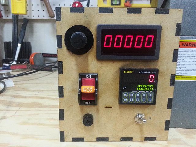
Tachometer - 0.56" DIGITAL Red LED Frequency and Tachometer Rotate Speed Meter DC 7-12V
Preset Counter C3E-R-220 - 110V 220V 6 Preset Digital counter 10KPCS Relay
(get the 110v - 220v relay version, 12v - 24v version will require an additional 12v power supply)
From Radio Shack - DPDT center OFF switch
This source is just for convenience, just get a DPDT center off switch with spade logs.
Neon Lamp
Again, get what you want, 120V will be the easiest to use.
The following parts are from www.sparkfun.com
Photo Interrupter GP1A57HRJ00F Breakout Board
Photo Interrupter GP1A57HRJ00F
Resistor 330 Ohm 1/6th Watt PTH
For those who would like to make the winder but might have trouble making the opto interrupter disk... here's the file in a format ponoko.com likes. Just upload it to them and they'll cut you one.
Their current pricing to make if for you is $5.33, so not bad at all. Make sure to specify these options -
Acrylic - Black
3.0 mm
P1 - 181.0 mm long x 181.0 mm wide
Making: $1.83
Material: $3.50
Total: $5.33
Schematic and control circuit - click to open the PDF - this is the layout to use if you're using the Harbor Freight lathe as your platform.
Theory of operation
Note:This is here for those that are interested in the how and why; it's not necessary to understand this section to build the winder. Also - this is rather conceptual in as much as the a low voltage relay is built into the counter already. You would only need to add an external relay like this one if you need to switch a large current load directly... a motor for example. Most controllers will use a low voltage trigger or inhibit line like the Harbor Freight lathe.
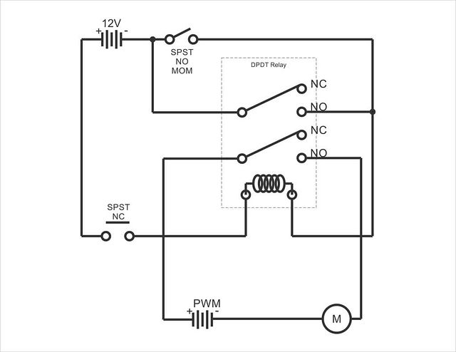
My design relies on a latching circuit for basic operation – so here’s how that works…
Here’s an animation I did to illustrate the basics of a latching circuit – you’ll find that this is directly relatable to the schematic posted below.
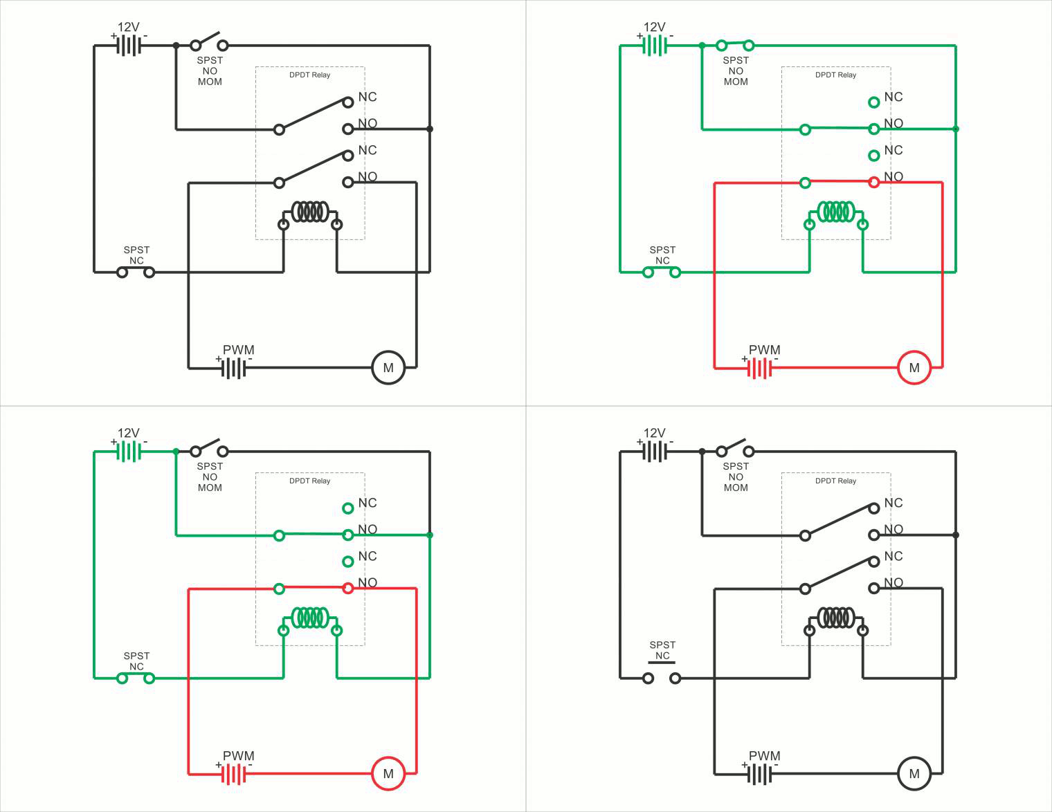 S1 is a momentary action switch, so it returns to it's original position after you press it, but while pressed, this is what the circuit looks like... S1 is pressed and latches the upper portion of the relay, both armatures move as one and the lower armature circuit completes the circuit between the motor and it's power supply, and the motor begins to run.
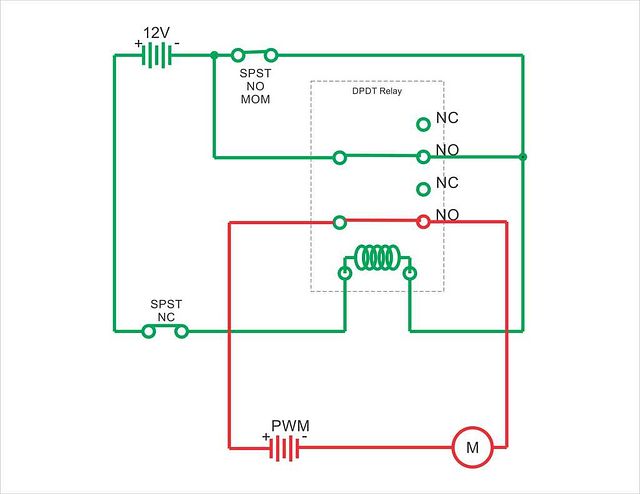 S1 is released, and through the nature of the circuit, the relay remains "Latched". The coil is still conducting and pulling both of the armatures into a closed condition and the motor and it's power supply are still bridged so the motor continues to run.
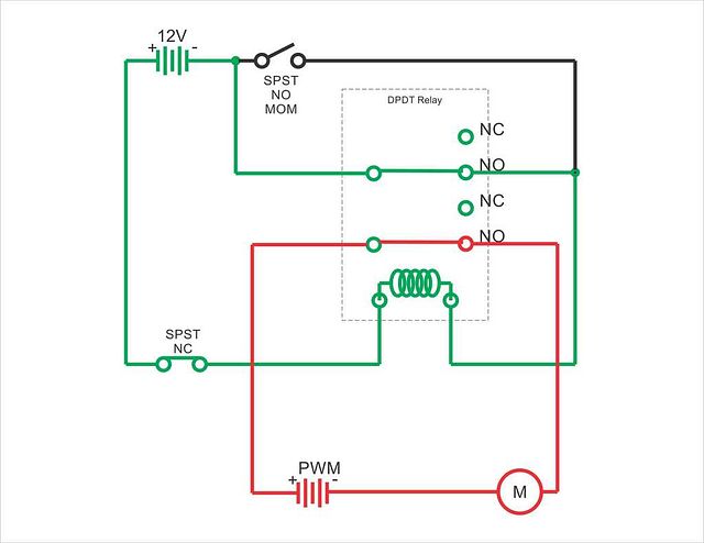 The momentary switch labeled S2 in this schematic represents the "normally closed" outputs of the counter's relay. Imagine that you have the counter set to spin until it reaches 10,000 winds and it gets there. The Normally closed contacts on the counters relay open, thus breaking the electron flow through the coil, thereby releasing the armatures, severing the circuit between the motor and it's power supply and the motor stops spinning. The circuit is now in a rest state and "unlatched". The circuit is reset and made ready to run again when you press the reset key on the counter, thereby closing S2.
Interfacing with the Harbor Freight lathe –
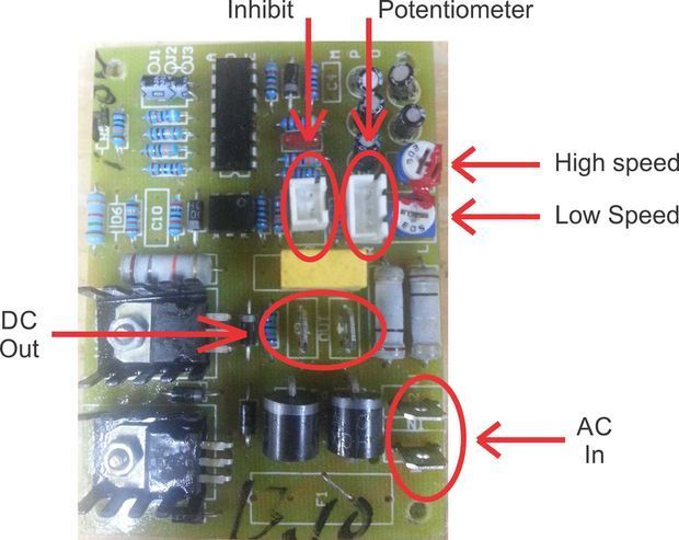 This is the motor control board for the Harbor Freight 8x12 wood lathe and probably several others.....
Here's how everything works -
DC out - motor for the lathe
AC in - AC input from wall (mains)
Potentiometer - (controls lathe min-max speed)
Inhibit - what we're using to stop the motor at the specified number of turns. Most commercial DC motor controllers have some variation on this theme... some provide braking and others, like this one, kill the DC voltage going to the motor. Other variations of lathes use this input for a type of safety circuit or to make sure chip guards are in place.
For some unknown reason of applied goofiness in engineering, on this lathe, this line was attached to a momentary push button switch labeled "circuit breaker reset"... whatever.
*** In this design, it's now connected to the "Normally Open" outputs on the counter module - when those outputs close when the preset count is reached, the motor controller shuts off. ***
As for the High and low speed adjustments, they do exactly what they sound like :-) - adjust the lower one to have the motor start at 0 RPM's instead of a "really not appropriate for this application" 750 RPM.
Opto interrupter disk and opto interrupter for counting winds
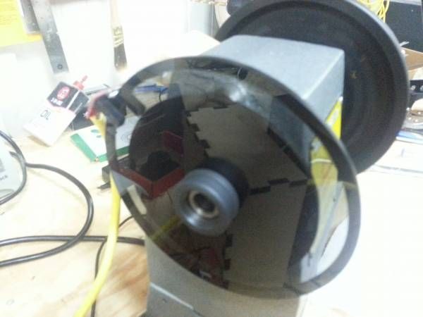
Here's a view of the left side of the lathe with the plastic bell housing removed showing the opto interrupter disk I cut and the assembly steps –
Spindle assembly ready for optical interrupter instillation (remove the plastic bell housing and the outer most jam nut) -
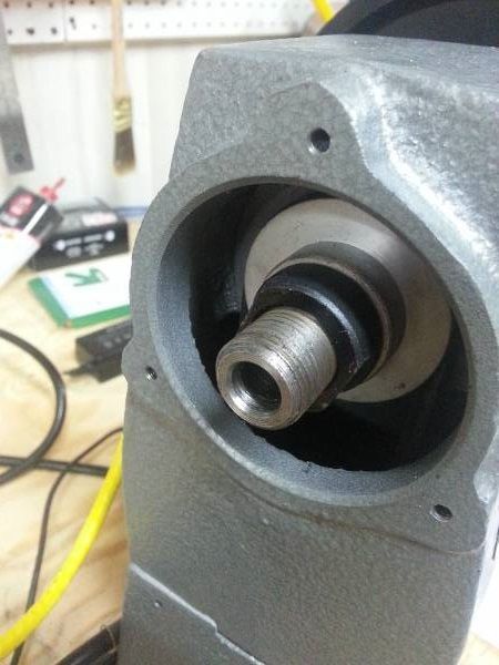 Place spacer on spindle shaft (I laser cut this spacer, but you could stack washers to achieve the same effect) -
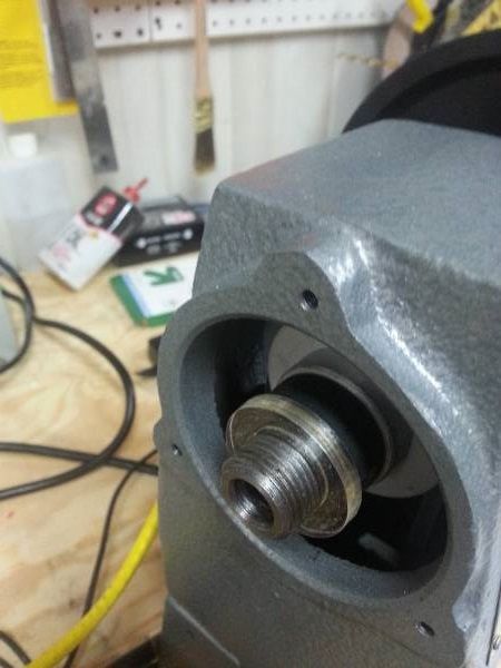 Spindle assembly ready to go with the new opto interrupter disk and outer jam nut installed – you need 2 windows on the disk and it needs to be well balanced, 3000 RPM is unforgiving in this area.
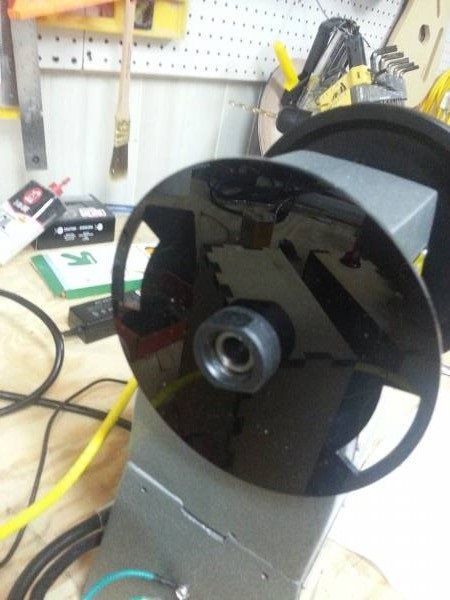 Under power at 3200 RPM – smooth as silk.
This photo shows the opto sensor on the top of the lathe – it just attaches with a magnet and hangs over the disk. I’ll take better pics of this area as soon as I get a chance.
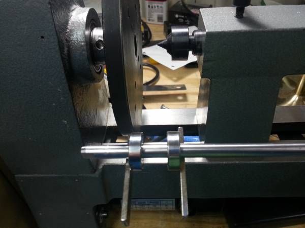
The winding bar is made from 10mm stainless stock (what I had laying around). You just need a piece of round stock that will fit in the opening of the cross slide (included with the lathe).
Magnetically adjustable wire guides
This innovation is kinda cool and works very, very well. The wire guides are 10mm ID ball bearings held in place and adjusted by magnets (way easier to adjust position then using set screws). Set screws are a pain, and not needed. It's super handy to be able to adjust the wire guides without fuss mid wind.
Buy ball bearings that fit your round winding bar from the previous step. McMaster Carr is a good source.
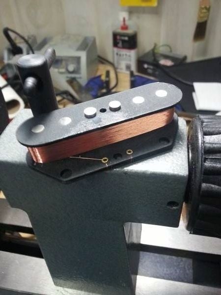
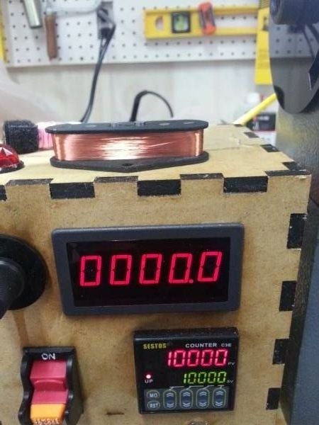
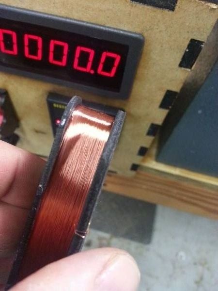
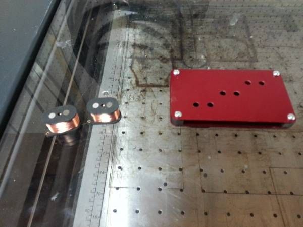
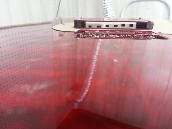
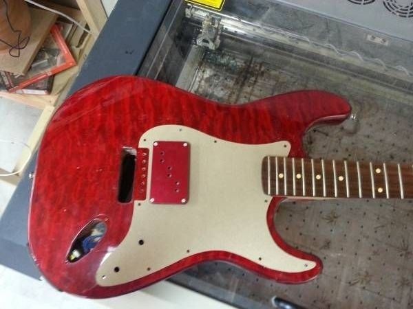
Handwound pickup goodness...
This winder is capable of producing some truly spectacular pickups - if there's interest, I'll do a start to finish on pickup making, from making the flat work from scratch (just like the ones above) to potting the pickup in wax and all points in between.
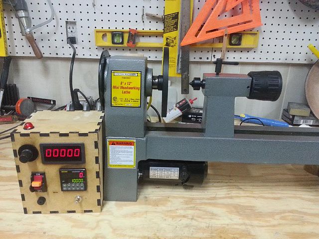
Comments
Thank you Marcelo, hope it's useful to you!
Very thanks Mojo! It's amazing.
Darryl, glad you like it and hope it helps out down the road. Thanks for
the compliment and kind words :-)
Great detailed blog Mojo,allways some knockers,i'm still on the old sewing machine,but this is a VERY good bunch of info for stepping up
It'll take a bit to put together though, can't video it myself
Yeah, I've watched most of them but I can never get enough of a good thing. Also I was responding to this excerpt from the article above.
Handwound pickup goodness...
This winder is capable of producing some truly spectacular pickups - if there's interest, I'll do a start to finish on pickup making, from making the flat work from scratch (just like the ones above) to potting the pickup in wax and all points in between.
I will check though to see if I've missed any new ones.
Would be extremely interested in a full video on the making of the pick ups. Awesome work!
-
1
-
2
of 2 Next